Product Manuals

How to Set Up Lora Gateways

Parts of the Lora Gateway

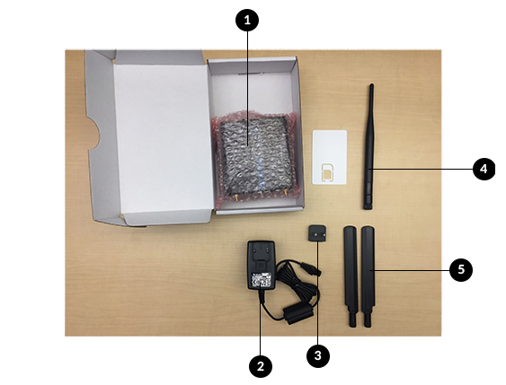
The Lora Gateway consists of:

  1. Lora Gateway
  2. Power Box
  3.  Adapter
  4. RF Antenna
  5. (2) GSM Antennas

General Rules and Knowledge for Lora

  • LoRa stands for Long Range
  • It’s low power and low frequency
  • Different regions have different frequencies
  • The device has the Spread Factor (SF) 7 – 12.
  • A spread factor of 7 is a shorter range and more ideal because it uses less battery
  • A spread factor of 12 is a longer range that will drain the battery faster
  • An ethernet cable is required to connect the Lora gateway to your computer as well as to troubleshoot
  • Never press the reset button for more than 30 seconds because it will erase everything

Assembling the Gateway

  1. Screw in the RF Antenna on the side with one port.
  2. Screw in both GSM Antennas on the side with two ports.
  3. Place the straight edge of the adapter in the power box first. Press down on the bottom to lock it in.
  4. Connect the assembling power cable in the back of the gateway into the associated port.
  5. After completing these steps, the gateway is physically assembled.

Establishing Power and Connection

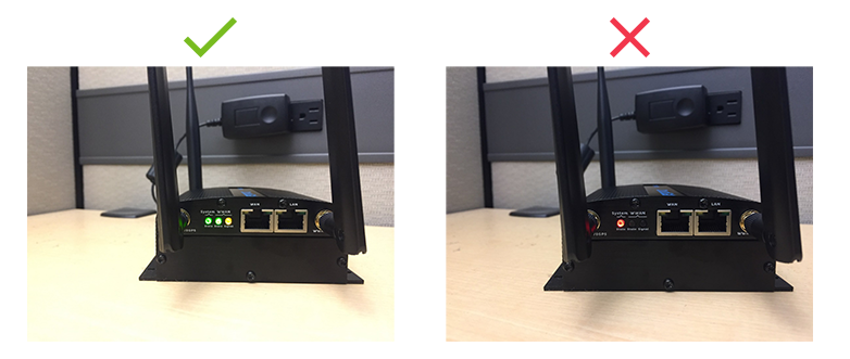
Plug the gateway in. The gateway will boot up and then look for a signal.

  1. Correct state is that System State is green, WWAN State is green, WWAN Signal is orange
  2. If System State remains red, there is a failure in the system.
  3. If WWAN State is red or orange, the gateway failed to connect